The BBC micro:bit is a pocket-sized microcontroller board designed to make learning programming and electronics easy and accessible, especially for students and beginners. It was developed by the BBC in collaboration with several partners like Microsoft, ARM, and the British Council, and was first released in 2016.
*Overview of micro:bit
|
Feature |
Description |
|
Microcontroller |
Nordic nRF52833 or nRF51822 (depending on version) |
|
Versions |
Version 1 (2016), Version 2 (2020) |
|
Programming Languages |
MakeCode (Block-based), Python (MicroPython), JavaScript, C++ |
|
Connectivity |
Bluetooth Low Energy (BLE), USB |
|
Power Supply |
USB, battery pack (2x AAA), or JST connector |
|
Dimensions |
52mm x 42mm |
* Micro:bit Board Configuration
There are two versions: V1 and V2. Here's a detailed configuration of each:
* micro:bit V1 Board Configuration
Microcontroller: Nordic nRF51822
ARM Cortex-M0 (32-bit)
16 MHz
256 KB Flash
16 KB RAM
Bluetooth Low Energy
Co-processor: NXP KL26Z
Manages USB interface and power regulation.
Key Features:
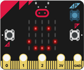
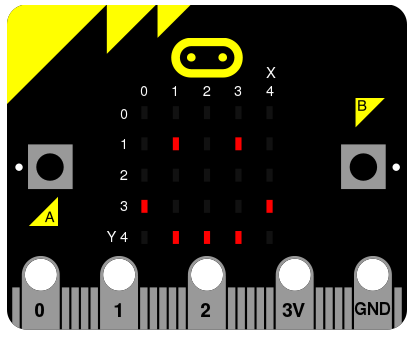
5x5 LED Matrix (25 red LEDs)
Two programmable buttons (A & B)
3-axis accelerometer (Freescale MMA8653)
Magnetometer (compass)
Temperature sensor (via accelerometer)
Bluetooth & USB connectivity
Edge connector (20 pins + 5 large ring I/O)
Light sensor (via LED matrix)
Power supply: USB, JST (3V battery), or edge connector
* micro:bit V2 Board Configuration (Released 2020)
Microcontroller: Nordic nRF52833
ARM Cortex-M4
64 MHz
512 KB Flash
128 KB RAM
Bluetooth 5.0
Co-processor: n/a (no separate USB chip — now integrated into the main MCU)
Upgrades Over V1:
Built-in microphone (MEMS mic with LED indicator)
Built-in speaker
Capacitive touch support (pin 0)
Power button with sleep mode
Additional flash and RAM
Improved accelerometer and magnetometer (Bosch BMX055)
Temperature sensor (dedicated)
Better power management
Edge connector compatibility with V1
* Edge Connector Pin Configuration
The micro:bit has a 23-pin edge connector, but only 5 large rings are accessible with crocodile clips. Here's a breakdown:
* Large Pins (Ring Connectors)
|
Pin |
Function |
|
0 |
Analog In / Touch / GPIO |
|
1 |
Analog In / GPIO |
|
2 |
Analog In / GPIO |
|
3V |
Power Out (3V) |
|
GND |
Ground |
? Edge Connector (Detailed Pinout)
|
Pin |
Function |
|
0 |
Analog in / Touch / GPIO |
|
1 |
Analog in / GPIO |
|
2 |
Analog in / GPIO |
|
3 |
GPIO |
|
4 |
GPIO |
|
5 |
Button A |
|
6 |
LED Column |
|
7 |
LED Column |
|
8 |
GPIO |
|
9 |
GPIO |
|
10 |
Analog in / GPIO |
|
11 |
Button B |
|
12 |
LED Row |
|
13 |
SPI MISO |
|
14 |
SPI MOSI |
|
15 |
SPI SCK |
|
16 |
GPIO |
|
19 |
I2C SCL |
|
20 |
I2C SDA |
|
3V |
3V Output |
|
GND |
Ground |
* Programming the micro:bit
Block-Based (MakeCode): Drag-and-drop interface. Great for beginners.
Python (MicroPython): Text-based programming. Good for more control.
JavaScript: Supported in MakeCode.
C/C++: For advanced users using ARM mbed platform or SDKs.
You can program it via:
Web USB (drag and drop .hex files)
Bluetooth (wireless programming via app)
Direct from the browser (WebUSB in supported browsers)
* Power Options
Micro USB (5V input) — via computer or USB adapter.
Battery Pack (2x AAA) — using JST connector.
Edge Connector Power Pins — 3V and GND.
* Accessories and Expansions
Breakout boards (to access all 20 edge pins)
Robot kits
Sensor modules
Grove expansion boards
IoT kits (Wi-Fi, LoRa modules)
Wearable kits (with conductive thread)
** Typical Applications
Educational coding and STEM projects
Robotics and automation
Games and interactive storytelling
IoT experiments
Data logging (sensors)
Wearable tech (via conductive thread)
Bottom of Form