Overview:
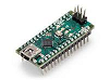
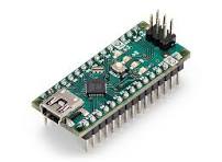
The Arduino Nano is a compact, breadboard?friendly microcontroller board from Arduino. It’s designed to give much of the power of an Arduino Uno in a much smaller form factor.
Originally released around 2008, the classic Nano uses the ATmega328P microcontroller. There are newer variants like the Nano Every, Nano R4 etc.
Technical Specifications (Classic ATmega328P Nano)
|
Parameter |
Value |
|
MCU |
ATmega328P (8?bit AVR) |
|
Clock Speed |
16 MHz |
|
Operating Voltage (logic) |
5 V |
|
Input Voltage (recommended) |
7?12 V (if powering via Vin) |
|
Max Input Voltage (limits) |
~6?20 V depending on the version / components |
|
Digital I/O Pins |
14 pins (D0?D13) |
|
PWM Digital Pins |
6 pins (D3, D5, D6, D9, D10, D11) |
|
Analog Input Pins |
8 pins (A0?A7) |
|
Flash Memory |
32 KB (of which ~2 KB used by bootloader) |
|
SRAM |
2 KB |
|
EEPROM |
1 KB |
|
Maximum DC Current per I/O Pin |
40 mA (absolute max) |
|
Dimensions |
~45 mm × 18 mm |
Pinout and Key Functionalities
Here’s how the pins are arranged and what they can do:
|
Pin / Group |
Function / Notes |
|
Power Pins |
* Vin – external input (7?12 V) when not using USB. |
|
Digital I/O (D0?D13) |
Can be used for general purpose digital input/output. |
|
Analog Inputs (A0?A7) |
Used to read analog voltages, via the ADC on the MCU. A4/A5 are also used for I2C (SDA/SCL). |
|
Communication Interfaces |
* Serial (UART) – using D0,RX and D1,TX. |
Things to Keep in Mind / Limitations
While each digital I/O pin can source or sink up to ~40 mA, staying near the maximum is risky. Best practice is to stay well below this (e.g. 20?25 mA) to avoid overheating or damaging the MCU.
The AREF pin should be handled carefully; using it incorrectly could damage analog inputs.
The Vin pin expects unregulated input; input voltage higher than what’s safe for the onboard voltage regulator (plus heat dissipation) can cause issues.
Some “Nano” board variants (Nano Every, Nano R4, Nano 33 IoT etc.) have different microcontrollers, operating voltages (many are 3.3 V), USB connectors, or extra features. So always check which variant you have.